The Language of Buildings

I recently stumbled upon a video, courtesy of YouTube's algorithm, from a 1969 BBC documentary series called Civilisation, hosted by the British art historian Kenneth Clark. In the video, Clark stands outdoors in Paris, offering a simple yet eloquent reflection on the history of civilization. “What is civilization? I don’t know. I can’t define it in abstract terms—yet. But I think I can recognize it when I see it,” he says, gazing at the iconic Notre-Dame Cathedral. With its elegant flying buttresses, pointed arches, and spires reaching towards the heavens, this Gothic masterpiece tells a story.

Fast forward half a century, and that same medieval wonder, which took nearly 200 years to build, was ravaged by fire in 2019. How easily something can be destroyed, even if it took lifetimes to create. Our buildings require time and effort to provide not only shelter but also something greater—a sense of identity and continuity. Winston Churchill captured this sentiment during World War II when London’s finest architecture—from Gothic to Tudor, Victorian to Edwardian—was being reduced to rubble. As if civilization itself was teetering on the brink. Standing before the House of Commons in 1943, amidst the destruction, Churchill delivered a profound speech: “We shape our buildings, and afterwards our buildings shape us.” His words echoed a resolve to rebuild, to carry forward the spirit of creation and renewal.

I carry that torch with deep reverence for the great builders who dedicated their lives to constructing enduring works. Recently, I passed by San Francisco's Beaux-Arts City Hall, home to one of the largest domes in the world, even taller than the U.S. Capitol Dome in Washington, D.C. I am always struck by its symmetry, intricate ornamentation, and sheer grandeur. It pulls me in far more than the neighboring buildings—bland skyscrapers with flat facades and glazed glass, telling no real story. When we build, let us imbue our creations with a language that speaks to the human experience, rather than reducing them to mere utility or return on investment. For the true return on investment is for humanity—our future generations.

Which Insulation Is Right For Your Home

The Importance of Insulation in Bay Area Homes

Insulating your home is crucial for maintaining comfort and energy efficiency, especially in the Bay Area. Located in Climate Zone 3, defined by the California Energy Commission (CEC), this region experiences moderate temperatures year-round with low humidity, mild wet winters, and warm dry summers. To meet energy efficiency standards, state and local authorities require specific insulation types, each with a unique R-value. The R-value indicates the insulation's ability to resist heat flow, calculated using the conduction equation: H = A x ∆T/R, where “H” represents heat, “A” is surface area, ∆T is the temperature difference, and “R” is the R-value of the building component (Joseph Lstiburek).

In this article, we’ll explore how insulation works, the consequences of inadequate or poorly installed insulation, and the various types available in California. Most importantly, we’ll help you determine the best insulation for your home, whether you're remodeling or aiming to improve energy efficiency and comfort.

How Insulation Works

Insulation is essential to prevent heat loss from sources like furnaces or radiant heated floors. Without insulation, the outside temperature would mirror the inside, making it impossible to maintain a comfortable indoor environment. To understand insulation’s role, we must delve into the science of heat transfer, which occurs through conduction, convection, and radiation (Radiant Barrier, Wikipedia).

  • Conduction: The flow of energy from a warmer area to a cooler one through a material.

  • Convection: The transfer of heat through fluids, like air or water, which is less relevant in residential construction.

  • Radiation: Electromagnetic waves that transfer heat, absorbed or reflected by materials.

The goal in construction is to create a thermal envelope, a barrier that minimizes heat loss to the outside environment, akin to a hot air balloon that must be airtight to maintain pressure and heat. Any gaps in this envelope compromise a home’s ability to retain heat, leading to increased energy costs and discomfort (Charlie Wing)

Challenges of Inadequate Insulation

When insulation is inadequate or improperly installed, several issues can arise:

  • Thermal Conductivity: Materials with high thermal conductivity allow heat to escape quickly, undermining the effectiveness of your home’s thermal envelope.

  • Thermal Bridging: Gaps in insulation create paths for heat to escape, leading to uneven temperatures and potential moisture problems.

  • Ghosting: In older homes, areas with inadequate insulation may develop "ghosting," where cold spots collect dust due to slower particle movement, known as Brownian motion (Joseph Lstiburek).

Choosing the Right Insulation for Your Home

When selecting insulation, consider the following factors:

  • Cost-effectiveness

  • R-value

  • Toxicity and flammability

  • Ease of future maintenance

  • Sustainability

  • Suitability for your climate zone

  • Best placement within your home

  • Moisture control and vulnerabilities

Spray Foam

Spray foam insulation, made from petrochemicals and additives for flame retardancy, comes in open-cell and closed-cell forms. Open-cell foam is less dense, providing acoustic benefits and breathability for building materials. Closed-cell foam is denser with a higher R-value, offering superior air sealing and moisture control. However, the high cost and potential health concerns from the petrochemicals used in spray foam make it a less appealing option for some homeowners.

Insulating Concrete Forms (ICFs)

ICFs are insulation boards combined with masonry or reinforced concrete, often used for foundation insulation. They provide excellent thermal resistance and structural support, making them ideal for energy-efficient home foundations.

Rigid Panels

Rigid panels offer continuous insulation, particularly effective around foundation footings where thermal bridging is common. These panels are made from similar materials as spray foam but are prefabricated, making them a practical choice for specific applications.

Structural Insulated Panels (SIPs)

SIPs consist of rigid insulation sandwiched between plywood or OSB, providing both insulation and structural support. While they reduce thermal bridging, the connection points can still pose a challenge.

Fiberglass Batts and Blankets

Fiberglass batts and blankets are common insulation materials, available in precut sections or continuous rolls. Made from molten glass, they can include vapor barriers for added protection. Mineral wool, such as Rockwool, offers excellent fire resistance.

Natural Fiber Insulation

Hemp and cork fiber insulation are sustainable options, though they may present fire hazards depending on composition and placement. Traditional methods like clay-impregnated straw provide good R-value, with the added benefit of clay's fire-retardant properties.

Conclusion: Choosing the Best Insulation for Your Home

Selecting the right insulation for your Bay Area home depends on various factors, including cost, effectiveness, and environmental impact. For most homeowners, a balanced approach that combines affordability, safety, and energy efficiency is key. Whether you’re leaning towards spray foam, rigid panels, or natural fibers, it’s essential to consider the specific needs of your home and climate zone.

If you’re planning a remodel or simply looking to enhance your home’s comfort and efficiency, I can help guide you through the insulation selection process. As a general contractor with experience in Bay Area construction, I’m here to ensure your home is insulated effectively and sustainably. Contact me to discuss your project and take the first step towards a more comfortable, energy-efficient home.

Footnotes:

  1. Charlie Wing, The Visual Handbook of Building and Remodeling (The Taunton Press, 2009), 370.

  2. Joseph Lstiburek, Moisture Control for Residential Buildings (Building Science Press, 2020).

  3. "Radiant barrier," Wikipedia (online).

  4. "Building insulation material," Wikipedia (online).

The Three Fundamental Conditions From Ancient Architectural Philosophy

Henry Wotton, a late renaissance author said "Well building hath three conditions: Commodity, Firmness, and Delight," which comes from his 1624 book, The Elements of Architecture. This was a translation from the great Vitruvius, a Roman Architect, that wrote a multi-volume work on architectural theory, De architecture, 17 centuries prior to Wotton’s. De architecture is the only known text to have survived from antiquity in regard to architecture.

Since the fall of the Roman Empire, most of the written works on how and why Romans constructed magnificent buildings were almost entirely lost to history. The Renaissance was a period of great revival of Ancient Greek and Roman art, science, and engineering in Europe.

Vitruvius’ work inspired those such as Leonard Da Vinci to draw out perfect proportions in architecture and the human body, such as the Vitruvian Man.

This Wotton’s phrase elegantly summarizes the foundational principles of architectural design and theory, which are still relevant today.

  • Commodity (Utility) refers to the functionality and utility of a building. It emphasizes that architecture should serve the needs of its users, providing convenience and suitability for the activities for which it is intended.

  • Firmness (Strength) involves the stability and structural integrity of a building. It underscores the importance of a building being safely constructed and durable, capable of standing solidly and fulfilling its intended lifespan without requiring excessive maintenance.

  • Delight (Beauty) focuses on the aesthetic appeal and the pleasure architecture can provide to both its occupants and passersby. This aspect encourages architects to consider beauty and artistic expression in their designs, aiming to elevate structures beyond mere utility to become sources of inspiration and joy.

Wotton’s articulation of these three conditions essentially provides a framework for evaluating good architecture, suggesting that a well-designed building must meet these interdependent criteria to be considered successful. This triad also reflects the Vitruvian principles of 'Utilitas, Firmitas, and Venustas' (Utility, Strength, and Beauty), highlighting a timeless connection to classical architectural philosophy that still holds true today.

When deciding on what to design and build, I’ll be sure to go back to these fundamentals that was the bread and butter for these ancient builders. Every detail, large and small, should address these three conditions.

Components Under a Slab

Rough underground plumbing for a bathroom. The toilet is upstream from all the branches - therefore, each fixture has a dedicated vent.

There are several key components that must be considered when remodeling a ground floor that requires a new concrete slab. In this example, I go through one of my recent projects for a master bathroom and closet conversion.

Every new ground floor slab for a residential home should have at least all of the following:

  1. A firm and dry soil condition.

  2. Proper sand and aggregate for embedding underground sewer waste and venting for each fixture (when necessary).

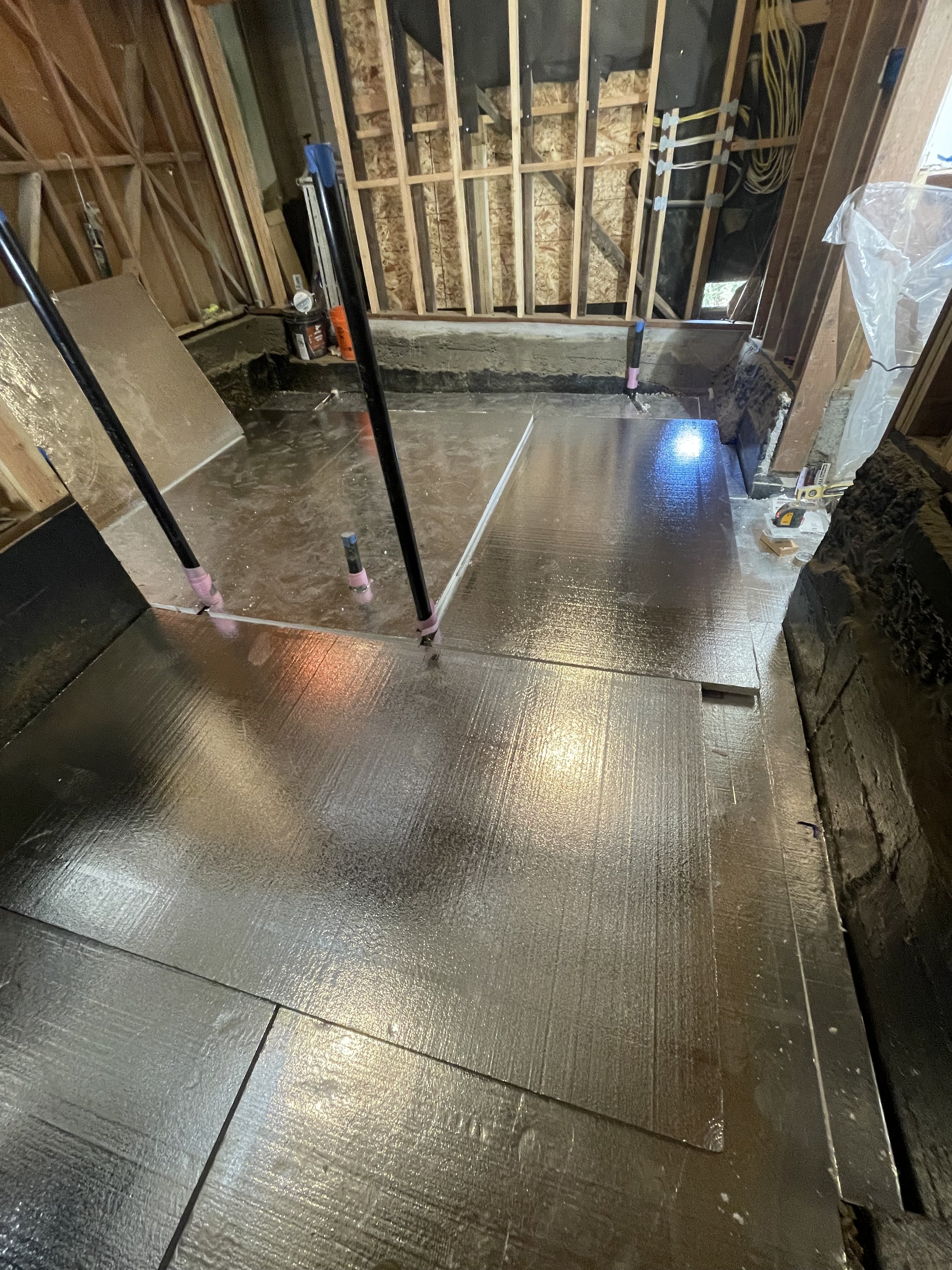
  3. Insulation that can withstand the weight of the slab as well as any dead and live loads that go above it.

  4. At least 10 mm vapor barrier to prevent moisture from going into the conditioned space above.

  5. Approximately 4 inches of poured concrete with adequate rebar (min #4) or proper wire mesh.

A layer of round aggregate was tamped down over the plumbing.

A layer of granular drainage pad (course grave with no fines) was tamped over the plumbing so that it offers an equal distribution to hold the weight above without adding too much pressure over the ABS pipes and proper drainage of moisture build up from the ground below.

Two layers of rigid board insulation were laid over the rocks. The top layer of rigid boards are staggered over the seams to prevent cold joints from rising up into the bathroom. Instead of taping the seams, there will be vapor barrier that will cover the entire area.

I set a laser for the desired surface layer of concrete to be poured over the insulation boards. The slab required approximately 4 inches of reinforced concrete.

A 10 mm vapor barrier was then laid over the insulation boards and the seams and edges were sealed with a vapor barrier tape.

Controlling groundwater entry by eliminating all below-grade openings requires installing waterproofing barriers or membranes. These membranes are typically placed on the exterior of perimeter foundation walls and beneath basement floors, as illustrated above. The assemblies must resist the hydrostatic pressures likely to develop and provide continuity between the exterior foundation wall waterproofing and the waterproofing under the basement floor slab. Such waterproofing systems are generally exceptions in most residential construction and are employed when the foundation is designed to be at or below the water table. Additionally, the foundation must be designed to withstand the uplift and buoyancy forces generated by groundwater. [1]

#4 rebar tied in a grid to keep the poured concrete in tact and less liable for cracking if voids form below the slab.

Footnotes:

Lstiburek, Moisture Control for Residential Buildings, Building Science Press 2020, 47.

Construction Waste and Contingencies

Here we subcontracted a waste bin at a job site in Oakland, CA. Several costs needed to be addressed for the estimation. What are costs to rent the bin and for how long? What does local county say about requiring a No Stopping sign and how much would the fees be? All of these factors must be addressed during the planning phase.

Understanding Construction Waste

Construction wastes from building and remodeling is often hard to predict and often more than you think. It places a burden on the contractor and client when one underestimates the amount it would take to clear out the wastes from a job site. This can happen when estimators include waste factors (by getting more material due to the size and bulk order it comes in from the manufacturer or by including extra material in case labor work requires more of it). Some common wastes from building construction are as follows:

  • Wood: Timber, plywood, MDF.

  • Inerts: Concrete, asphalt, bricks.

  • Metals: Steel, copper, aluminum.

  • Plastics: PVC pipes, packaging.

  • Other: Glass, insulation, drywall.

We need to find a better solution of predicting and estimating how much waste will accumulate during the demolition, construction, and finishing phases of a building project while considering eco-friendly routes for each designated waste.

Sustainability Considerations

As an estimator and builder, I would need to figure how to minimize the amount of waste in each building phase. Reduction during the pre-building phase needs to be well drawn out, considering every possibility where waste will accumulate.

  • Start with Planning: Minimize waste through detailed planning. Using accurate measurements and then depending on the waste product, add a 10% waste factor which will help estimate the cost it will take to rent or build a waste bin; demo and remove the material; and include transport and waste facility fees.

    How many trips will it take given the size of your waste bin? Do this for every phase of the job description. Just when you think you have the estimation costs down to a tee, the amount of building material might be overestimated and your left with more waste than you previously thought; thus, requiring more trips.

  • Material Selection: Choose durable, long-lasting materials. The material used for fixed structures, such as framing, metals, appliances should come with high quality and a long warranty. This will raise the price of the quote but a reputation of good workmanship demands good quality material.

  • Recycling & Reuse:

    • Sorting: Allocate separate bins for wood, inerts, and metals.

    • Recycling Centers: Identify nearby recycling facilities. Are you using your own company vehicle or subcontracting the transfer and disposal of the waste.

    • Reuse Materials: Utilize salvaged materials where possible.

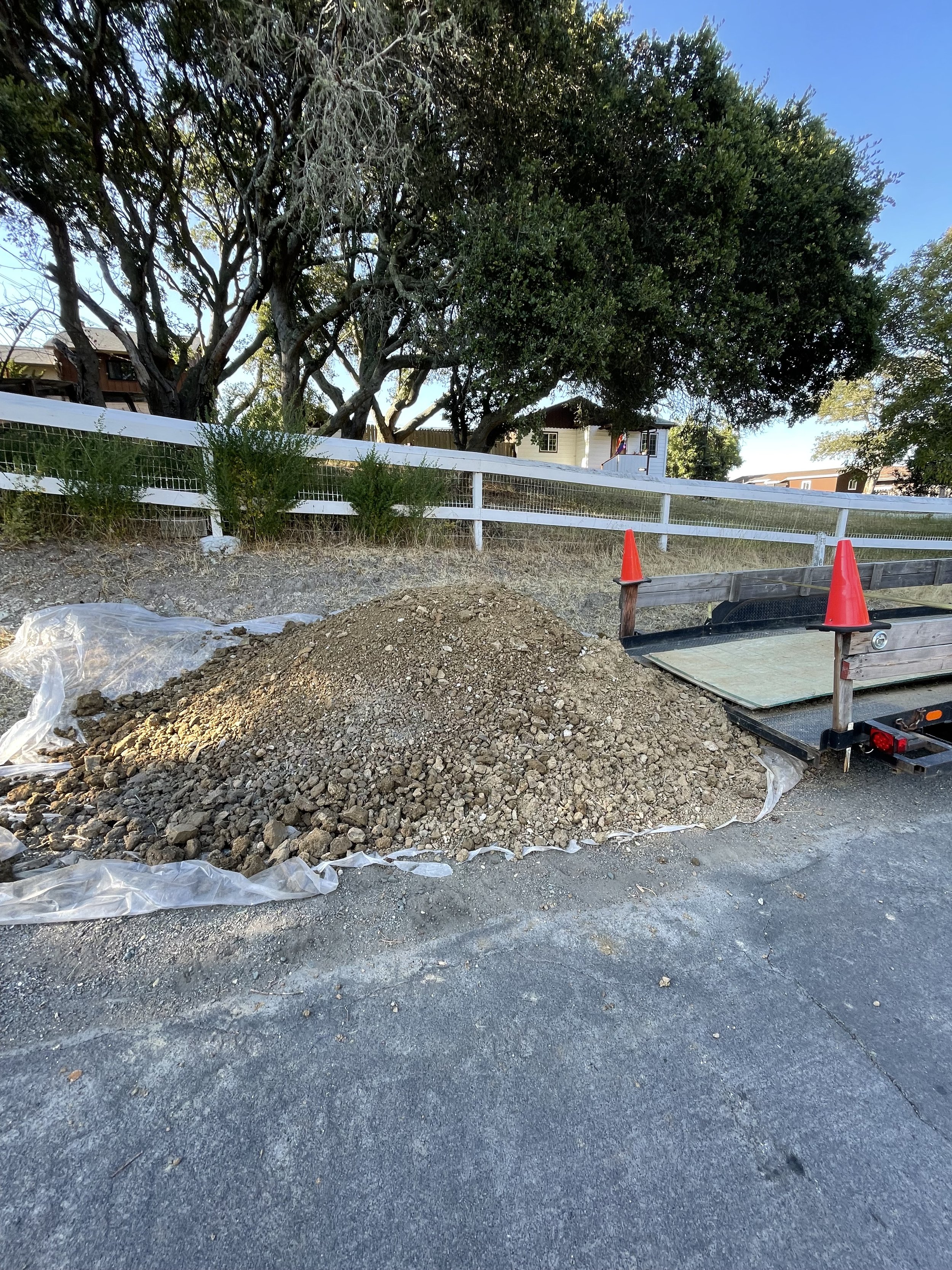
Here we transferred excavated soil from the job site to a nearby neighbor that needed it for his own project.

Logistical Considerations

Placing a dedicated bin at the job site will help to sort and allocate various waste products.

As a contractor, become familiar with the surrounding area of the job site.

  • Availability of waste facilities within the area.

  • Local ordinances and regulations (permits, hazardous waste materials that need special contracts, barricades and containment of waste)

  • Prices and delivery from local waste truck companies.

  • The conditions of the roads leading to the project. This is an important one — can large trucks reach the job site safely and not obstruct public roads?

There is so much indirect field costs to estimate and I found waste management one of the more difficult areas in estimation. A lot of it came from experience but having a well drawn out and deliberate method of estimating enables to create less burden for building construction estimation.

Moisture Control for Crawlspace

Foundation Assemblies : Crawlspaces

A crawl space or crawlspace is an unoccupied, unfinished, narrow space within a building, between the ground and the first (or ground) floor. The crawl space is so named because there is typically only enough room to crawl rather than stand. [1]

In Residential Construction there are three foundation assemblies:

  1. Foundation slabs

  2. Crawlspaces

  3. Basements

In this topic, we are focusing on crawlspaces and its varying fundamental approaches to construction and use of moisture control.

History behind crawlspaces

Crawlspaces became popular in the 20th century US residential homes as it was a cost-effective alternative to basements in areas where the climate or ground conditions made basements impractical or unnecessary.

Historically, crawlspaces provided a convenient space for the installation of plumbing, electrical systems, and HVAC components, keeping these elements protected yet accessible for maintenance. They also elevated the home off the ground, which helped prevent issues related to moisture and pests, particularly in damp or termite-prone regions.

The choice of a crawlspace over a basement or a slab foundation typically depends on regional practices, climate, and economic factors prevalent at the time of construction.

Traditional crawlspaces often have simple ductless vents that connect the outside environment to the inside crawlspace by a “grill” barrier to prevent animals from getting in. This causes the environment within the crawlspace to be non-conditioned. [2]

Problems with Traditional crawlspaces

Traditional crawlspaces allow air circulation underneath houses. Heat from residents and heating systems warms the subfloor, keeping the floor framing dry and warm. However, this is not efficient because existing insulation is often inadequate and the occupant’s will often pay more in energy costs.

Even by increasing the insulation in the walls and subfloor, we are making the crawlspace more susceptible to increasing vapor pressure, moisture content, and leaving the non-conditioned crawlspace vulnerable to rot.

Signs of moisture problems include mold growth, musty odors, condensation, wood rot, and pest infestations.

By performing regular inspections to detect any of these signs, we can then find solutions to prevent a future disaster from occurring.

two types of crawlspaces to consider

As a homeowner, what do you want out of your existing crawlspace?

There are two main solutions to updating your crawlspace:

  1. Keep the crawlspace vented and non-conditioned (air exchange is flowing freely from the crawlspace and its outside environment).

  2. Convert crawlspace as “not vented” and conditioned (air exchange is connected internally between crawlspace and the house or by dehumidification).

The most cost-effective improvement is number 1. If you see the crawlspace for it’s utility use, such as easy access for future plumbing and electrical work. You can save money by keeping your crawlspace vented and non-conditioned.

The second option, by converting your crawlspace into a conditioned space, you are thus controlling its temperature and relative humidity. This will allow you to stow away luggage, equipment, and any belonging you have without needing to worry about mold growth.

preventive measures

The number one issue to divert groundwater away from the home.

  • Proper exterior drainage systems (gutters, downspouts, grading).

    • Are the downspouts that connect to your gutters are properly connected to underground pipes that lead the flow of rainwater away from your home?

    • If the ends of the downspouts are exposed, is there a solid concrete padding that is sloped so that the run-off can lead away from the house and not directly to its foundation?

  • Install a 10 mm vapor barrier inside the crawlspace to fully encapsulate the ground floor from the crawlspace.

  • Insulate the floor joists with insulation recommended by local code and then cover with rigid board plus a protective board to prevent pests and fire.

Vented Crawlspace Detail


vented crawlspace improvement by viking wood

Insulate the Subfloor

Here we added R19 insulation in the floor joists in the crawlspace area.

Rigid insulation boards were then nailed below.

10 mm Vapor Barrier over Ground Floor

Once the rigid insulation boards were all nailed up and sealed, the vapor barrier was then laid out and taped.

Footnotes:

  1. “Crawl space,” Wikipedia. Last modified April 28th 2024. https://en.wikipedia.org/wiki/Crawl_space

  2. Joseph W. Lstiburek. “Moisture Control for Residential Buildings,” Building Science Press. 137.

What is a Shear Wall in Residential Construction?

Definition of a Shear Wall

A shear wall contains vertical shear panels or slabs that resists shear forces in its own plane due to wind, earthquake forces, or explosions and thus stiffens the structure against deformation by such forces. [1]

The main structural system in light framed homes are its foundation and framing system. They must resist various loads which causes stress to the structure itself. All loads are a type of stress and can be reduced to two terms: tension and compression. [2]

  • Tension: forces that stretch and pull.

  • Compression: forces that press, push, or squeeze.

The origin of the word “shear” in old English is to ‘cut through with a weapon’. [3] So think of a shear wall as the most vulnerable area in a home that could be strained by any of those two forces explained above. However, in today’s language, a shear wall is a wall that is already reinforced to withstand various loads. These loads include:

  • Live Loads: Moving loads such as occupants, snow, and rainwater

  • Dead Loads: Static loads such as the weight of home itself including as the fixed structure such as cabinetry, appliances, and furniture.

  • Seismic Loads: Forces from impact loads, shock waves, and vibrations.

  • Wind Loads: Negative and positive pressure buildup within the house and its exterior environment.

What is a Shear wall made of?

A shear wall, as mentioned above contains panels or slabs. In conventional light framed homes, these panels are usually made of plywood according to standards by the Engineered Wood Association (www.apawood.org). Plywood (cross-laminated wood veneer) or oriented strand board (OSB) are common panels used as sheathing for the exterior walls, floors, and roofs of most light framed homes. [4]

Sheathing is like skin for a building's frame made of studs attached to the foundation. It's meant to protect against air and moisture, providing structure and strength.

A deeper look in the terminology is that a shear wall is a component of structural sheathing. Every shear wall contains sheathing but not all sheathing is a shear wall.

APA Sheathing Panels

Each panel of plywood or OSB has an APA Grade Stamp. Which is the performance standard from Engineered Wood Association. The APA acronym, which stands for American Plywood Association is the trade organization’s previously held name, and is shown as stamp on each sheet of panel.

Source: Engineered Wood Association

1. Panel grade

2. Span rating

3. Tongue and groove

4. Bond classification

5. Decimal thickness declaration

6. Mill number

7. Product standard

8. Performance Category

9. Siding face grade

10. Species group number

11. HUD recognition

15. Panel face orientation


installing apa wall sheathing for shear wall

Wall sheathing panels can be installed vertically or horizontally but certain considerations must be made. If the foundation is on a relatively flat surface, panels can be installed vertically where the strength axis is parallel to the studs. However, if the foundation is on a slope or contains a stepped foundation, it would be wise to orient the panels horizontally to prevent a ‘domino effect’. This horizontal orientation is applied with strength across studs.

A 1/8” spacing is recommended at all seams, edges and corners, unless the APA manufactured panel indicates otherwise. [4]

All edges of the panel shall be fastened onto a stud or blocking installed between the studs. Horizontal sheathing requires a lot more blocking since they are made 4 feet in height, whereas the vertical sheathing can ideally go from the sill plate all the way to the top plate if the height is 8 feet.

structural design IMplications

A shear wall is made to be incredibly stiff and resists the vertical and horizontal forces acting on its plane. Therefore the internal forces within the shear wall created complications if things fail.

There are four critical failure mechanisms that should be understood when designing structural supports on walls. [5]

  1. Vertical shear

  2. Horizontal shear

  3. Flexural failure

  4. Buckling

The four critical failure mechanisms in shear wall when the force acting on the shear panel is greater than its resistance.

Figures 1-4 are prime examples of lateral forces acting in-plane on the shear wall panel. Figures 1-3 are common during earthquakes; however, figure 4, is an example of axial loading during compression in-plane.

Buckling has been an issue since the beginning of housing construction. It was not until a polymath named Leonard Euler found a solution to the elastic buckling problem in 1759. The problem was finding a formula where high ratio of length to thickness columns, in this case a shear panel, would buckle while being overloaded on its axis but would recover to its original position once unloaded. [1]

Shear Wall solutions

  • The solution to shear wall panels from buckling are in its thickness, size and type of nails, and nail pattern. Finding the adequate thickness to prevent Eulid in-plane buckling is important as well as Eulid out-of-plane buckling when lateral torsion is acting on the panel.

  • Fortify openings, such as windows and doors, by using wall bracing and continued shear panels all around. This is known as the coupling effect. Neighboring walls can transition any lateral forces so that the energy transfer in the house due to any of loads mentioned above can safely move back down to the ground. Shear wall at adjacent corners are great to prevent torsional stress and gyrations.

  • Nail pattern: follow the local county for nail patterns as well thickness of the APA rated sheathing. I found it intuitive to increase the number of nails towards the ends of the house. For example if the house is on a slope. The frequency of nails on the panels should increase towards the lower end of the slope.

  • Shear wall panels are not limited to residential homes but large commercial buildings as well.

code and standard provisions

Provisions and design tables are made from the International Building Code (IBC) along with the Special Design Provisions for Wind and Seismic (SDPWS).

IBC: Section 2305 General Requirements for Lateral-Force-Resisting Systems

2305.1 General. Structures using wood-frame shear walls or wood-frame diaphragms to resist wind, seismic or other lateral forces shall be designed and constructed in accordance with AWC SDPWS and the applicable provisions of Sections 2305, 2306 and 2307.

Continuous Load Path

A continuous load path from the roof to the foundation is required per SDPWS Section 4.1.1

Source: Simpson Strong-Tie

Once a continuous load path has been determined for the shear wall and each partition has been fastened with the right type fastener, look to the SDWPS table on shear capacities.

Below is the table for nominal capacity of shear wall panels for both seismic and wind loads.

To understand the graph below, let me explain a couple variables in the table:

  • V = induced unit shear, plf (pounds per linear foot)

  • G = apparent diaphragm shear stiffness from nail slip and panel shear deformation, kips/in (1000 pounds-force per inch)

Source: SDPWS

For better resistance to lateral forces, use a thicker panel with more nails, placed closer together, and longer nails in earthquake and windy regions. Follow IBC and SDPWS rules, unless local regulations differ.

calculations for shear walls

Deformations and elasticity should be determined depending on length and height of your shear wall. “If a shear wall deflects an inch, its connections will also need to be able to travel the same distance without breaking the system.” [7]

Let’s do an example of a force-transfer shear wall with a large window opening in order to find what type of plywood and nails to use given the dimensions below:


If we want to be within the requirements of a 3,500 lb lateral wind load, we will need to find the compression and tension forces acting on this wall with the given dimensions.

T = C = 3,500 x 8’ (height)/15’ (span) = 1,867 lb for both Compression and Tension.

We’ll use the Diekmann Technique Analysis by treating each sheathing area to act like its own beam, carrying shear and flexural forces at either end. [7]

The Diekmann Technique treats the entire wall as one unit and will provide the limits to the nominal shear capacities for Table 4.3A.

In the schematic above, you can see the mechanics involves in each zone. For the following schematic below we will list out these zones by letter.

Let’s start with zones B and G. They are each 4’x4’ and will need to resist a total of 3,500 lbs. Our goal is to figure out the force in pounds per linear foot in each zone.

3,500 lb / (4’ + 4’) = 438 plf for both zone B and G for horizontal forces.

Zone D and E will need to resist a total of 1,867 lbs.

1,867 lb / (1.5’ + 2.5) = 467 plf for zone D and E for vertical forces.

We assume that the tension and compression cancel out at the mid-point of Zone E (i.e. the window sill) and bottom of Zone D (bottom of header). In other words those two horizontal lines that intersect the midpoint of Lines 2 and 3 = 0 lb in either compression and tension.

The difference between those midpoints and line 7 is 3.5’.

The T & C located on Line 2 and 7 and Line 3 and 7 = 467 plf x 3.5’ = 1,635 lb

Zones F & H on the horizontal: v = (1,635 lb/4’) = 409 pff = 438 pff - 29 plf

Zones A & C on the horizontal: v = 29 plf by symmetry


Finally, check the Maximum Induced Unit Shear from ASD. [8] In this case, 467 plf from zones D and E in the Diekmann analysis to that of the nominal value by multiplying by 2.0.

467 plf x 2.0 = 934 plf (nominal).

Look back at Table 4.3A to the Wind column and go down the nearest number by rounding up. You will find 980 plf is the capacity for 7/16” plywood with 8d galvanized nails on 4” nail spacing.


Footnotes:

  1. Henry J. Cowan, “Science & Building: Structural and Environmental Design in the Nineteenth and Twentieth Centuries,” A Wiley-Interscience publication. (1978): 350

  2. Julia McMorrough, “The Architecture,” Rockport Publishers, Inc. (2008): 72

  3. "New Oxford American Dictionary (Second Edition)".

  4. Charlie Wing, “The Visual Handbook of Building and Remodeling: A Comprehensive Guide to Choosing the Right Material and Systems of Every Part of Your Home,” The Taunton Press, Inc.: 196-205

  5. “Shear Wall,” Wikipedia, last modified on April 22nd 2024, https://en.wikipedia.org/wiki/Shear_wall

  6. See footnote 1: 18

  7. Shearwall Design with 2015 SDPWS from Simpson Strong Tie Learning Center

  8. “ASD Diaphragm Shear Forces,” Simpson Strong Tie, https://seblog.strongtie.com/2014/12/wood-shear-wall-design-example/


Oliver's Corner

AI rendered photo of a carpenter using Euclidean geometry


As a builder, I'm eager to share the insights I've gained with the hope that they prove as beneficial to my readers as they are to me. Throughout my career, I've navigated various building trades and delved into office accounting, drawing, and planning. My ultimate ambition is to become a master builder and to expand my sharing platform beyond mere word-of-mouth.


To achieve this, I believe in adopting a student's mindset first—eagerly acquiring skills and knowledge while continuously fueling my curiosity. I also find that writing down my thoughts and feelings helps me articulate them more clearly. Therefore, I plan to maintain a weekly blog, which I anticipate will not only keep me committed to my path and purpose but also inspire my readers to pursue their own passions, whether as a career or a hobby and maybe learn a thing or two along the way.

Ground Floor Seismic Retrofit

Most homes here in San Francisco are built from locally forested redwood lumber with little to no insulation, lath and plaster walls and ceilings, and foundations without reinforced concrete. These simple materials used in building beautiful homes from Victorian to mid-century has certain drawbacks to today’s standards for health and safety. In retrospect, we should give credit to the craftsman, architects, engineers, and regular homeowner builders for doing the best they could given the supplies they had at their disposal (however, violations of building codes and lack of building knowledge should not go unnoticed which happened back then as it does now). Today’s concerns are the use of lead in building materials from plumbing to painting as well as the use of asbestos from ductworks to insulation.

Here is a 2x6” redwood framing with exterior siding. This the ground floor garage of a 1916 three story Edwardian home. Notice the horsehair lath and plaster on the ceiling. It was tested negative for asbestos just in case due to rewiring, installing a new ductwork, and a new gas line.

In this topic I examine the use of seismically retrofitting the ground floor of a three story Edwardian home.

Know Your Wood

There was evidence of termite infestation in the crawlspace, most of the studs that held up the house were of the Red Cedar specie — which is great as an exterior siding, but can be susceptible to termites that live in the Bay Area.

Replace Compromised Studs

In this case, I added redwood to replace the red cedar. Plentiful locally, redwood is a great deterrent against insects such as termite infestations and fungi as it contains a chemical agent called tannin, which gives off its reddish hue. Notice the hold downs are situated on the flat step and end of the foundation.

Stepped Foundation

Here is a schematic I did on SketchUp to represent the stepped foundation similar to the house I was working on.

When constructing a building with a stepped foundation, it is essential to ensure that the hold downs are placed at the same height across the different levels. By aligning the hold downs at the same height, you can maintain the structural integrity of the building and evenly distribute the loads to the foundation.

Having hold downs at consistent heights is crucial for providing adequate support and stability to the structure. It helps prevent uneven stress distribution, which can lead to structural issues over time. Additionally, uniform hold down placement simplifies the construction process and ensures a more cohesive and reliable foundation system.

By paying attention to the alignment of hold downs on a stepped foundation, builders can enhance the overall strength and durability of the building. This meticulous approach to construction will help create a sound infrastructure that can withstand various external forces and provide long-lasting protection for the occupants.

Blocking

I installed blocking so that the edge of each plywood can be nailed and further strengthen the lateral forces of the vertical studs to prevent a domino effect.

The sill plate, located between the foundation and studs that fastened on top of it, tend to be wider than the studs itself. This poses a problem in seismic retrofits because you would ideally want the bottom of the plywood to be fastened to the sill plate so that the concentric forces during an earthquake can transfer back down to the ground.

In the photo above they concealed the sill plate with the foundation. Since this was a voluntary seismic retrofit, I added blocking at the base of the foundation to act as my sill plate. Each blocking was glued down and fastened with three structural screws. Every 4 to 6 feet had new 5/8” anchor bolts, even though there were existing anchor bolts.

Overall the idea was that the new blocking will act as my continuous sill plate for the plywood.

Insulation

Either side of the wall received proper insulation before covering it up with plywood. This will reduce exterior noise and prevent infiltration of cold and damp air.

Consider insulating and getting all wiring and plumbing done before you seismically cover the walls with plywood.

Staggered Plywood

I chose to stagger my plywood sine this was on a stepped foundation. The plywood covers both side of the home and into crawlspace.


Upgrade Your Home with Seismic Retrofitting and Shearwall Installation

Is your ground-level home prepared for the unexpected? At Viking Wood, we understand the importance of ensuring your home's structural integrity, especially in areas prone to seismic activity. Retrofitting your home with a shearwall is a wise investment that can enhance its resistance to earthquakes and provide you with peace of mind.

Why Choose Seismic Retrofitting and Shearwall Installation with Viking Wood?

  • Safety First: Protect your loved ones and belongings by fortifying your home against seismic forces.

  • Expertise: Our team of experienced professionals specializes in seismic retrofitting, ensuring the job is done with precision and care.

  • Quality Materials: We use high-quality wood and construction materials to guarantee the durability and longevity of your shearwall.

  • Peace of Mind: With a properly retrofitted home, you can rest easy knowing that your property is better equipped to withstand seismic events.

Don't Wait Until It's Too Late

Take proactive steps to safeguard your home today. Contact Viking Wood to schedule a consultation and learn more about how seismic retrofitting and shearwall installation can benefit your ground-level home. Upgrade your home with Viking Wood, because your safety is our priority.